robotic arts: motion & motors/fall 2012/ ADA Compliance / Health and Safety
contact: jrouvelle@mica.edu
office hours: tues/thurs 2-4pm ***please make an appointment if you'd like to see me during office hours, i'm often working with students in other rooms during those times so there's a chance i won't be in my office if you stop by without an appointmet.
week 1 , (classwork/assignment), week 2 , week_3 week_4, week_5 week_6 week 7 week_8 week_9 week_10 week_11 week_12 week_13 week_14, week_15

I was taught that the finished sculpture was maybe the end of the paragraph. Once a sculpture was completed it was critiqued and put back on to the scrap pile. This way of working taught me to think sculpturally rather than to think about sculpture. charles ray
please remember that we're here to make art projects. always consider the materials here sculpturally - i.e, how what you make for this class occupies visual space - meaning please account for all of the elements of your works here (from the micro-controllers to power cords to the movements your projects make) compositionally. realize that every element of your project is a mark of some kind. kinetic works move through time within visual space. in this class your work will be considered in terms of its relationships to temporal and visual space(s). use the techniques you learn here essentially. artists can do miraculous things with minimal material. work hard to create pieces that are distinguished gestures composed of authentic marks. work hard to get to the core of your interests and discoveries and develop artworks that reveal those discoveries simply and clearly.
- getting started with arduino - you can purchase a pdf version for $9.99
- arduino software
- online arduino tutorials that follow and supplement 'getting started with arduino', above.
- basic electronics, including soldering, common parts, etc..
- fritzing
What to buy-->
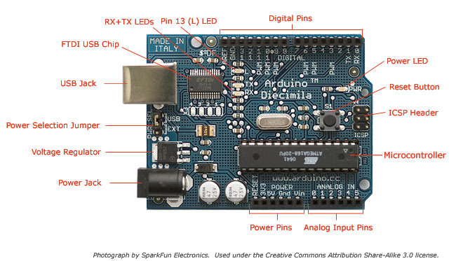
Arduino (uno or leonardo)
- from amazon (be sure to purchase a USB a-b cable, too!) OR
- from moderndevice (be sure to purchase a USB a-b cable, too!) OR
- sparkfun (be sure to purchase a USB a-b cable, too!)(shipping kind of slow)
- ArE YoU a KLutz?? then, perhaps you'd like to purchase the.... ruggeduino (be sure to purchase a USB a-b cable, too!) ?
- ***for any of the above, be sure to pick shipping that will get you the arduino quickly
- breadboard and wire kit # 03MB104WK
additional resources:
- softwear (***free ebook on wearables - lilypad/arduino, etc.)
- arduino
Make Magazine
instructables
leah beuchley intro to the lilypad arduino - practical arduino (book)
- 30 arduino projects for the evil genius
- google searches on lilypad, arduino
- youtube searches on lilypad, arduino
- conductive threads delicious page
- problemboard delicious page
where to buy stuff, online, and locally:
- electronix express
- bgmicro
- sparkfun
- moderndevice
- digikey
electronics goldmine (***slow shipping***) - all electronics
- baynesville electronics (***on joppa road - expensive, but in an emergency...)
- middle river hobbies (***motors, other hobby electronics gear***)
- servocity (***where to buy servo motors***)
- american science and surplus
- octopart (a search engine just for electronic parts)
***
introduction to the class, questions (yours), homopolar motor, G.R.I.M.E.
this class is about making things move with electronics. i encourage you to work slowly and carefully so that you build a personal practice that incorporates smart motor control. please don't dream up a project, then try to make it. start exploring materials and become a keen observer, and allow your projects to evolve from there.
"Adventures are precisely about not knowing, about having nothing to exchange that would hold the intellect in place within the knowledge economy, a form of epistemological poverty and hunger that concentrates the mind and propels it outside of itself, not towards the goals set by the master explicators but out into the infinite detours of intellectual discovery. To be adventurous is precisely not to arrive but, rather, to witness the arrival of the unexpected and the unpredictable." gary peters
contemporary grant cycles have existed for, what, maybe three generations? They require artists seeking funding to invent the meaning of a work before it exists, turning practitioners from all media into primarily conceptual artists, as they propose work to fit the expectations, models, and agendas of their funders. (Whereas, arguably, the next closest model - the patron model - created a different sort of relationship that favored longevity rather than project-by-project attention.) -jason eppink from a comment on this hyperallergic post
we'll be covering:
- basic circuitry
- motors
- arduino programming
- hardware hacking
- affordance programming
here we go!
G.R.I.M.E. IS AN ACRONYM FOR
Gravity
Resistance (friction, etc.)
Inertia
Momentum
Energy
when you're building you project, bear these terms in mind, and take a moment to glance at this page and see if you can find a way to describe what is happening using some those words.
art & tech
***the only rule in the class is that you are not allowed to shock yourself and die.
***here's another rule, neodymium magnets can harm your computer, SO DON'T GET THEM NEAR MY (your) COMPUTER!!!!
no more wire hangers
make this, experiment with it and realize a project:
feel free to integrate other materials into your work
remember the G.R.I.M.E.
at the end of class today we'll show what we did and please talk about your work using the words/concepts of G.R.I.M.E.
- order an arduino, breadboard-wire kit as linked above, and download 'getting started with arduino' **you must have your arduino for next class, please ORDER TONIGHT - and pay close attention to the shipping you choose.
-
What to buy-->
Arduino (uno or leonardo)
- from amazon (be sure to purchase a USB a-b cable, too!) OR
- from moderndevice (be sure to purchase a USB a-b cable, too!) OR
- sparkfun(be sure to purchase a USB a-b cable, too!)(shipping kind of slow)
- ArE YoU a KLutz?? then, perhaps you'd like to purchase the.... ruggeduino (be sure to purchase a USB a-b cable, too!) ?
- ***for any of the above, be sure to pick shipping that will get you the arduino quickly
- breadboard and wire kit # 03MB104WK
- review the exercises we covered in class.
your homopolar works
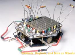
B.E.A.M. robotics, schematics, breadboards, free-forming.
let's make one!
we're going to make a BEAM robot today called a bi-core. we're going to
read the schematic
identify the parts
breadboard it
test it
free-form solder it
your homework will be to mod it
our guide will be this excellent tutorial by jerome demers
you will also now know about instructables!
here's the schematic and parts list
step 1
gather/identify the parts
step 2
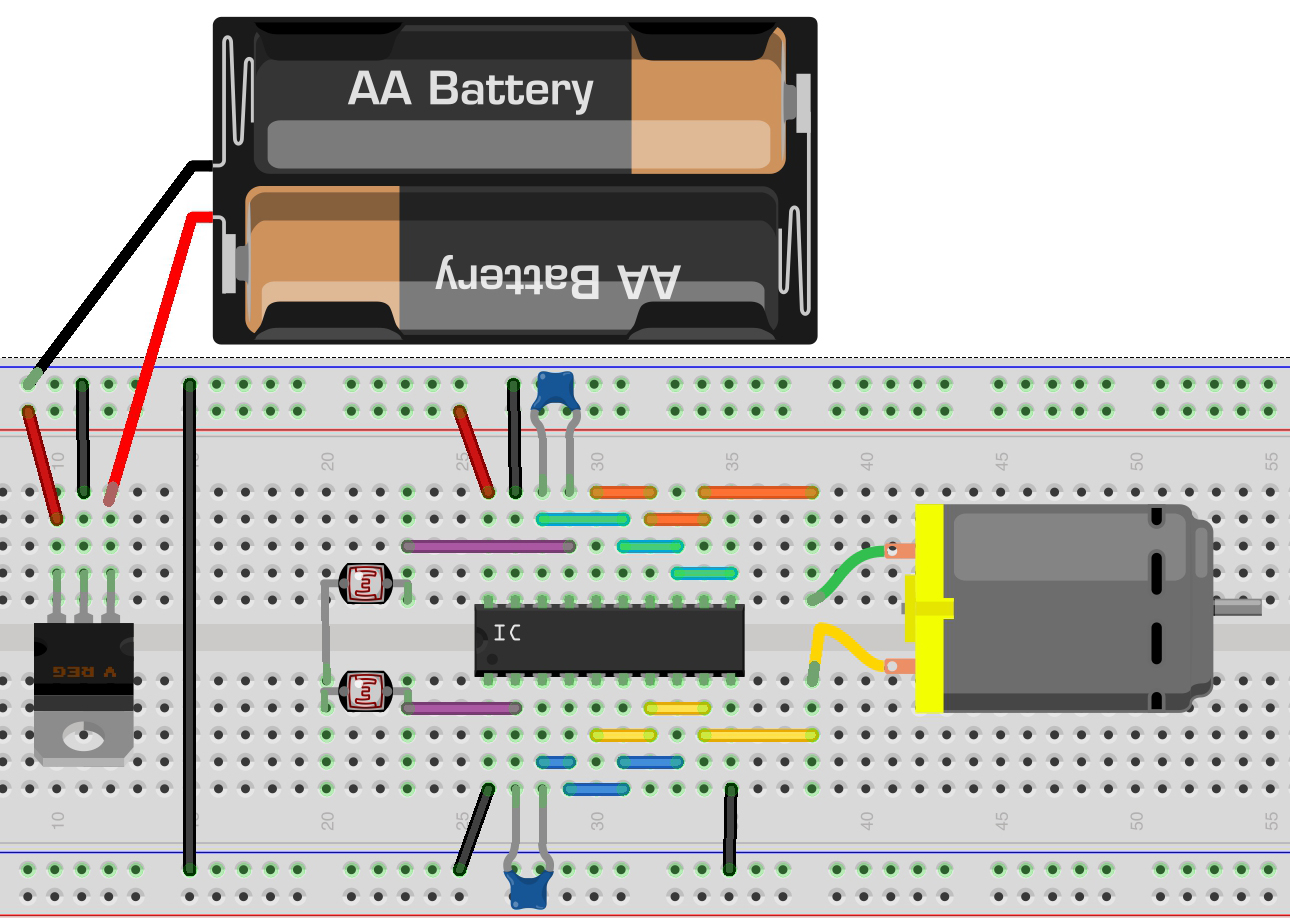
translate the schematic/circuit diagram/parts list onto a breadboard
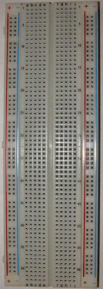
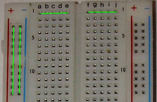
how breadboards work
step 3
breadboard it!
open this
take your time
step 4
check your wiring
power it
motor sound bad?
turbine oil
place small circles of glue stick on the shaft of your motors for traction
step 5
try different capacitors/resistors
observe how they change the behavior
step 6
take a break
free forming
***work in teams!!
we should have enough parts for you to be able to leave your breadboarded bi-core in tact, and use it as a reference for the free formed version
assignment
mod the bi-core
bring your work to class
today we'll complete the circuit for the bi-core walker and free-form solder a version of it with the 74ac240 as the brain
74hc240 vs 74ac240
these are two similar chips in the 7400 series
list of all the members of the 7400 series
our 74xx240 is an octal buffer - which means that its an electrical signal amplifier
the 74hc240 is more tolerant of higher input voltages but provides less current than the 74ac240
it can handle 9v but isn't quite as strong as the 74ac240
the 74ac240 can only handle a maximum of 7v, meaning you must use a voltage regulator if using a 9v battery
the 74ac240 delivers more current with less voltage, so it is actually a stronger power source for the motor.
add photo/light detection
Phototropic Suspended Bicore. This requires two photodiodes. Solder (or wire) the first photodiode's cathode to the second's cathode. Connect the first photodiode's anode to pin 2, the second anode to pin 17. The time-out will be dependent upon the light level.
A photodiode is a transducer (a sensor - it converts one energy into another) that takes light energy and converts it into electrical energy.
If placed in a dark room, the photodiode is exposed to no light; therefore it creates no electricity. However, if light falls upon it, it takes the light energy and produces electric current in response.
A photodiode conducts electric current directly proportional to the amount of light that falls upon it. It's a perfect direct relationship.
A photodiode operates in a circuit in reverse bias. This means that the anode (longer leg) connects to ground of the circuit and the cathode (shorter leg) connects to the positive voltage supply of the circuit. Current flows from the cathode to the anode when exposed to sufficient light.

***photodiodes are polarized. the shorter leg is the cathode (0,gnd), the longer leg is the anode (+), please be sure you have identified the anode and cathode prior to placing the photodiodes in your breadboard.
to make your Bi-Core respond to light, follow the diagram below.
the cathodes (shorter legs) are joined, and then the anodes (longer legs), go to pin 2 and 17 respectively. the cathodes (shorter legs) are joined - meaning place the cathodes of each diode in the same row on your breadboad.
the photodiodes are a replacement for the resistor.
please be sure this is working (i.e, the motor is spinning) before soldering!!
once you have both versions of the circuit working on your breadboard, get an extra 74ac240 + all other parts, and using your breadboarded version as a guide, follow this tutorial and free-form the robot.
be sure to carefully include the 7805 as a voltage regulator because the 74ac240 cannot handle more than +5v dc.
free-form/solder this circuit following:
***don't solder the resistor, just the capacitors!! (see below)
***you'll need to solder in the voltage regulator!! (do that last)
***work in teams!!
please don't solder anything until you are confident that you can both solder comfortably and that your circuit is put together the right way!
locate materials to build the body - remember how electricity moves across metal - avoid connecting legs of the robot to something metal.
assignment:
finish your mobile robot, bring them to class with a fresh battery!
bring your arduino!!
intro to arduino, transistors, pulse width modulation (controlling the speed of a reversible dc motor)
***please bring a laptop to class to work on - if you don't have one, please let me know!
***i'm here to help, but require that prior to asking me to look at your code you put comments in it (see below).
intro to arduino
download and install of the development environment from here
arduino sketches are comprised of (control) structures, variables, and functions
(control) structures. A program is usually not limited to a linear sequence of instructions. During its process it may bifurcate, repeat code or take decisions. For that purpose, C/C++ provides control structures that serve to specify what has to be done by our program, when and under which circumstances. if....then....
a variable is a portion of memory alloted to store a determined value.
A function is a block of code that has a name and it has a property that it is reusable i.e. it can be executed from as many different points in a C Program as required.
btw, what does 'void' mean?
Basically it means "nothing" or "no type"
There are 3 basic ways that void is used:
1) Function argument: int myFunc(void) -- the function takes nothing.
2) Function return value: void myFunc(int) -- the function returns nothing
3) Generic data pointer: void* data; -- 'data' is a pointer to data of unknown type, and cannot be dereferenced
Note: the void in a function argument is optional in C++; int myFunc() is exactly the same as int myFunc(void). It is required for a return value.
shall we?
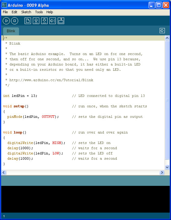
code example 1 ***when opening example sketches that you will make changes to, ALWAYS use Save As..:
1. examples-->basics-->blink
/*
Blink
Turns on an LED on for one second, then off for one second, repeatedly.
This example code is in the public domain.
*/
void setup() {
// initialize the digital pin as an output.
// Pin 13 has an LED connected on most Arduino boards:
pinMode(13, OUTPUT);
}
void loop() {
digitalWrite(13, HIGH); // set the LED on
delay(1000); // wait for a second
digitalWrite(13, LOW); // set the LED off
delay(1000); // wait for a second
}
2. upload it.
working?
how to debug your code using the Serial function
1. follow the link above, and copy/paste the code into a new sketch
2. upload it.
3. open the terminal window and watch what happens.
***the terminal window is a great help when working with the arduino. you can have your code send whatever you want to keep track of by using the "Serial.println(variable)" function.
4. to familiarize yourself with this functionality, add Serial.println to the Blink sketch like this:
/*
Blink
Turns on an LED on for one second, then off for one second, repeatedly.
This example code is in the public domain.
*/
void setup() {
// initialize the digital pin as an output.
// Pin 13 has an LED connected on most Arduino boards:
pinMode(13, OUTPUT);
Serial.begin(9600);
}
void loop() {
digitalWrite(13, HIGH); // set the LED on
Serial.println("high");
delay(1000); // wait for a second
digitalWrite(13, LOW); // set the LED off
Serial.println("low");
delay(1000); // wait for a second
}
5. upload it
6. open the serial monitor and see what you find.
ok?
controlling motors with the arduino
phase 1:
**there is code in the instructable, USE THIS INSTEAD
this will allow us to make the motor spin at different speeds in one direction only.
you'll need to solder wires onto a motor
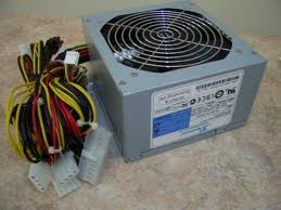
to be powering our motors we'll be using an ATX power supply.
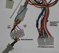
here's what each of the wires do:
we'll have to make a few adjustments to work with it. the first is stripping/soldering the green wire to any available black wire, like this:
now, carefully strip a red wire and another black wire. the red is 5vdc, the black is ground.
connect the red to a + bus on your breadboard, and the black to the ground bus.
connect a black wire from the arduino ground to the ground bus on the breadboard
**the arduino must share ground (common ground) with whatever it is controlling. DO NOT CONNECT THE RED WIRE FROM THE ATX TO THE ARDUINO!!!
once you have the motor and power supply ready, make the circuit and run the code
when you have the code functioning, experiment with changing the speed of the motor by changing the values from 0-255 in the code
speeding up and slowing down the motor
try this
in class exercise:
experiment with the two methods of controlling the motor so that you understand what each line of code does.
w5ek e/aka remembering brian austen green's rap record

arduino + h bridge = speed and direction control for dc motors!
controlling the speed and direction of a dc motor with an h-bridge
breadboard this:
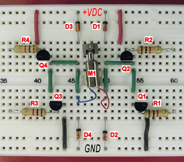
Parts list:
R1-R4 are 1k resistors
D1-D4 are diodes **note that diodes have a colored band on one end, insert according to the image above!
Q1-Q3 are NPN transistors
Q2-Q4 are PNP transistors
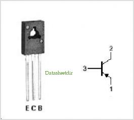
your transistors are in a different case than the ones in the image, you'll need to locate the corresponding pins to place the transistor properly in your circuit
note the metal tag on the body of the transistor, yours are in a package called t0-18
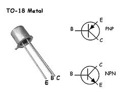
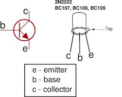
the package of the transistors in the circuit image is called a t0-92, this is a standard transistor package. note the flat side of the head.
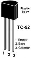
compare and transpose:
![]()
now build the h-bridge, call me over when you're done so i can take a look, then
connect the 5vdc (red) wire from the ATX to the very top row of the board (+VDC). Connect the ground of the ATX (any black wire) to the very bottom row of the board (+GND).
connect the ground (gnd) of your arduino to the ground of the breadboard.
the + from the arduino will never connect to the + of the breadboard!!!
test it (you don't need the arduino yet):
t0 try it out, connect a wire from GND to the right-side of R2.
then, connect a wire from +VDC to the left-side of R3.
the motor should spin forward.
yes?
ready for some code?
arduino connections (use the image above as a guide):
pin 9 - R1
pin 10 - R2
pin 11 - R3
pin 12 - R4speeding up/slowing down in different directions?
now we change gears

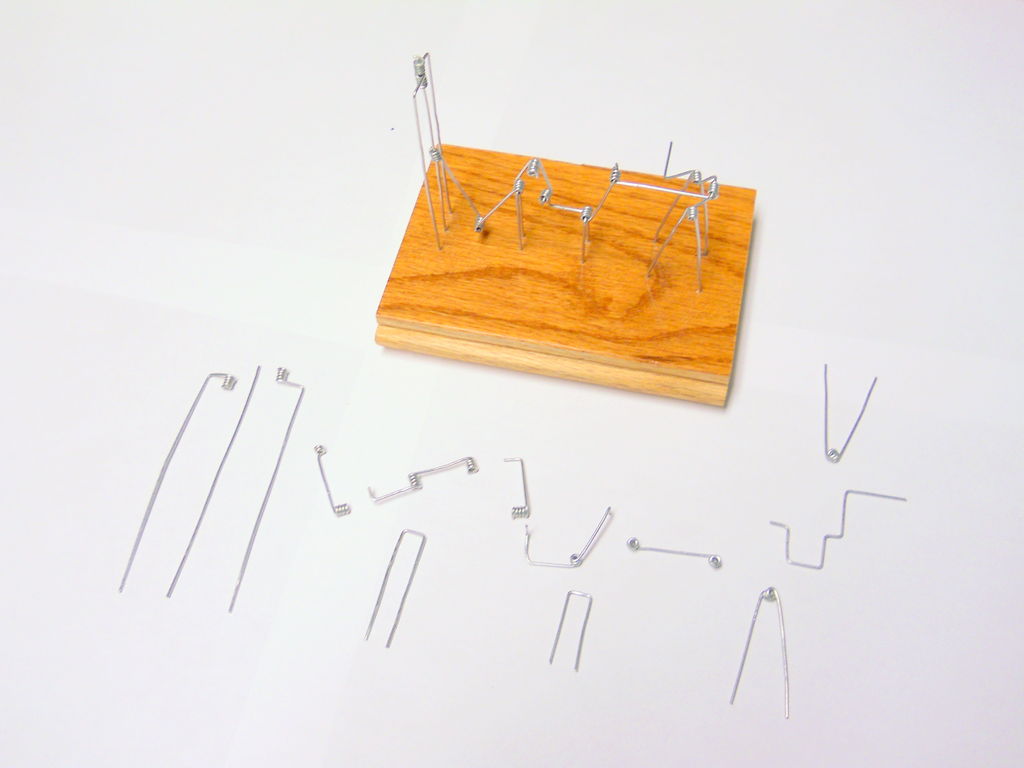

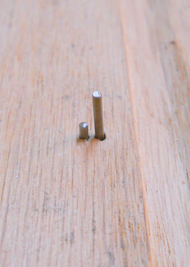
make a jig to create the shapes (you can also use your hand and a thin nail)
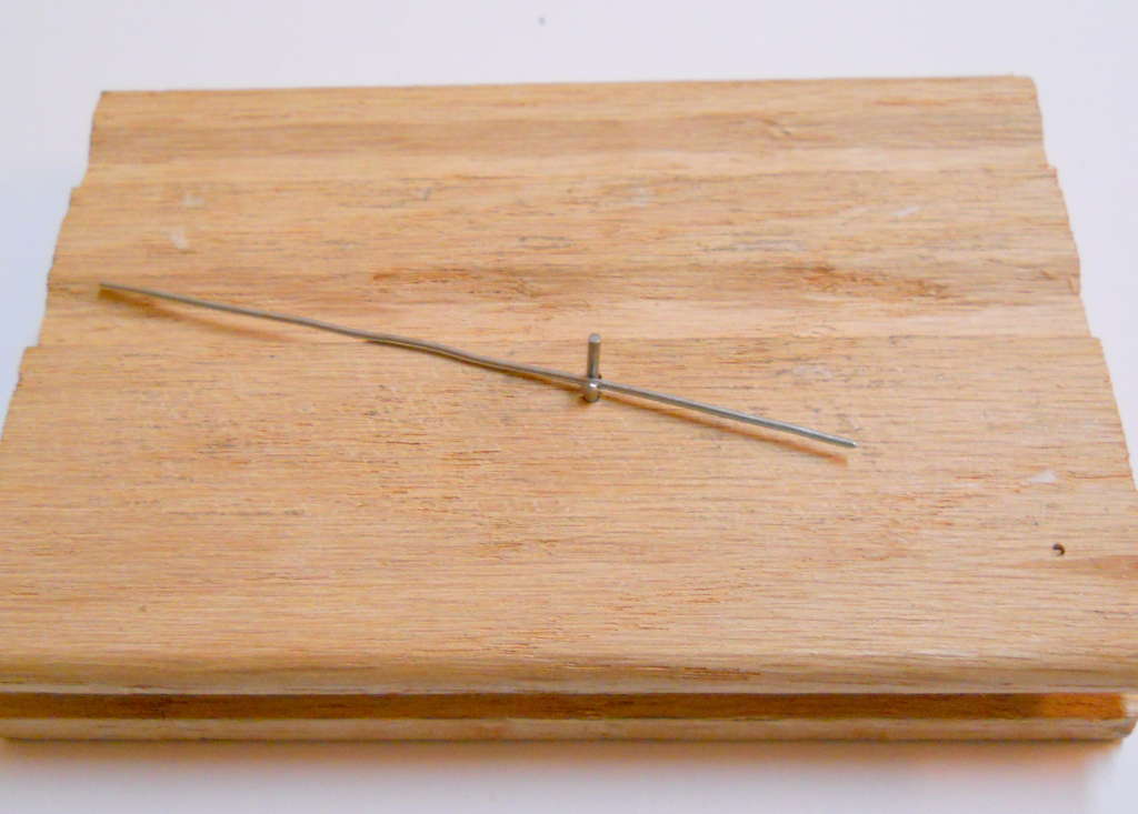
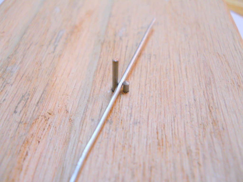
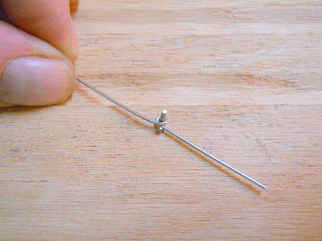
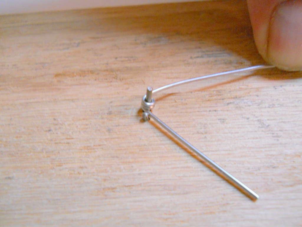
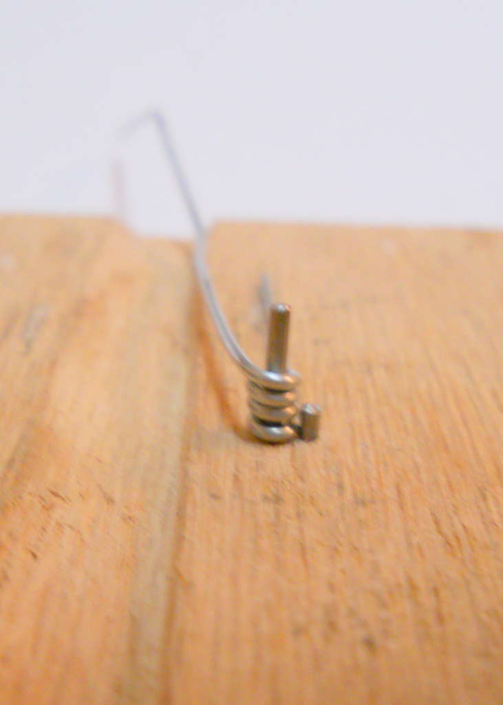
assignment
make a paper clip machine
make a gear out of whatever you have laying around:
foam, plastic, wood
press fit the gear to the shaft of your motor
connect the crank of your machine to the gear
run the code for the h-bridge....
hint: the crank will be replaced by your motor, so bear that in mind.
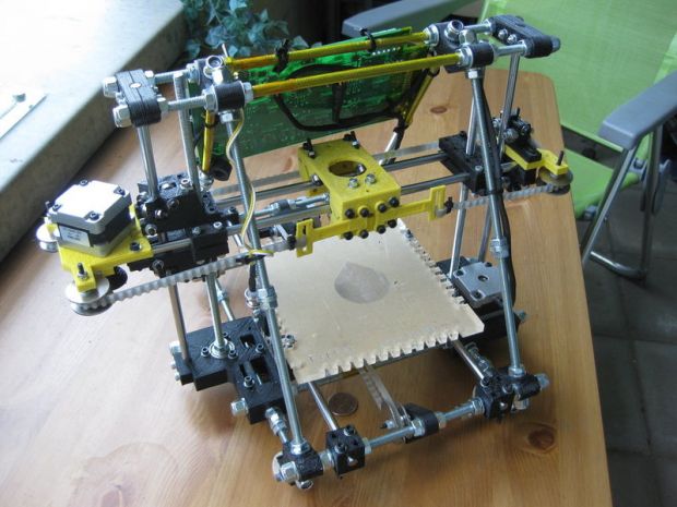
making gears with the robot called reprap, some inspiration for your projects
"it's all geometry, process, and materials"
inspiration
small kinetic sculptures by larry lawrence
various mechanisms and automata by denha
MIT Architecture from Paper Fortress on Vimeo.
the reprap
dr. adrian bowyer, inventor of the reprap
tool chain - you'll need these opensource software packages to print your gears
the details:
I.
openscad tutorial from makerbot
quickstart openscad to make a simple 'gear'
openjscad gear generator *** you don't need openscad if you use this app.
To create your own gears, launch Google Chrome and point your browser to:
joostn.github.com/OpenJsCad/gearsdemo.html
code examples, enter this code into openscad and then Design->compile
1.
cylinder(2,5,5);
2.
cylinder(2,5,5);
cylinder(10,1,1);
3.
difference() {
cylinder(2,5,5);
cylinder(10,1,1);
}
4.
difference() {
cylinder(2,5,5);
cylinder(10,1,1);
translate([3.5,0,0]) cylinder(10,1,1);
}
when you have your model in openscad, follow these steps to prep it for netfab studio basic
openscad -- export your file as an .stl
Design --> compile and render
Design--> export as .stl
Ia.
skip openscad and get a model/.stl from somewhere else, like
thingiverse or
II.
the point of netfab is to create/correct your openscad .stl file/model in advance of converting it into gcode.
do this:
project--> new
repair
automatic repair
default repair
execute
part-->
export part --> export as .stl
III.
slic3r converts your watertight .stl model into gcode
IV.
pronterface -- scroll down for versions. interface with reprap, parse g-code and extrude model
assignment
complete a motorized paperclip machine with your reprap printed gear attached to your motor, controlled by the h-bridge connected to the arduino
your paperclip machine h-bridge reprap gear projects
a new, stronger h-bridge for new, stronger motors, for much more info on using transistos read this
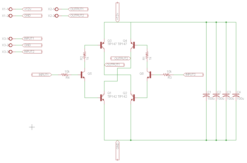
**TIP142 (Q1,Q2) are NPN transistors
we'll be using part # BD437 as our NPN transistors, the connections are the same.
**TIP147 (Q3,Q4) are PNP transistors
we'll be using part # BD442 as our PNP transistors, the connections are the same.
***notice that in our new transistors the base is pin three!!!
>>our h-bridge will be able to handle 45V 4A <<
parts list:

2x npn transistors, notice the circuit diagram to the right of the image, on the picture below the npn are the N-channel FETs
2x NPN , part # BD437
2x pnp transistors, notice the circuit diagram to the right of the image, on the picture below the pnp are the P-channel FETs
2x PNP, part # BD442
2x NPN transistors, part # 2N2222
2x 10k resistors
brown-black-orange-gold
**some high current resistors don't have colored bands, their values are printed on them.
2x 1k resistors
brown-black-red-gold
**some high current resistors don't have colored bands, their values are printed on them.
open this circuit image in a new tab
build it!
to test this circuit before you connect it to your arduino
connect +5V from your ATX (red wire) to the plus bus of your breadboard
connect grnd from your ATX (black wire) to the ground bus of your breadboard
connect the ground of your arduino to the ground bus
DO NOT CONNECT +5V FROM YOUR ARDUINO TO THE BREADBOARD
ground input 1
connect input 2 to +5v from your arduino...
spinning?
code
assignment
make a motion study by connecting this motor to an object of your choice and coding varied movements

strong(er) motors!
new motor: servo
where to buy stuff
what to look for
dc or ac?
**we've only looked at reversible dc motors so far. we'll be getting into ac motors soon, but we won't be controlling their speed. if you need to control an ac motor now, buy one of these.
volts
**we've only worked with motors in the 3-12 VDC range. your recent h-bridge can handle motors up to 36VDC, don't exceed 36VDC!
current
**measured in amperes (ah) or milliamperes (mA). your h-bridges can safely handle 4 ah. motors over 10ah require special circuitry that costs about $30, like this
rpm
geared?
size
**we're about to start working with a servo motor, and to do so, we'll need to cut/strip three wires.
1. DISCONNECT YOUR ARDUINO FROM YOUR USB PORT!!!
2. wire your servo and connect it to the arduino like this --->
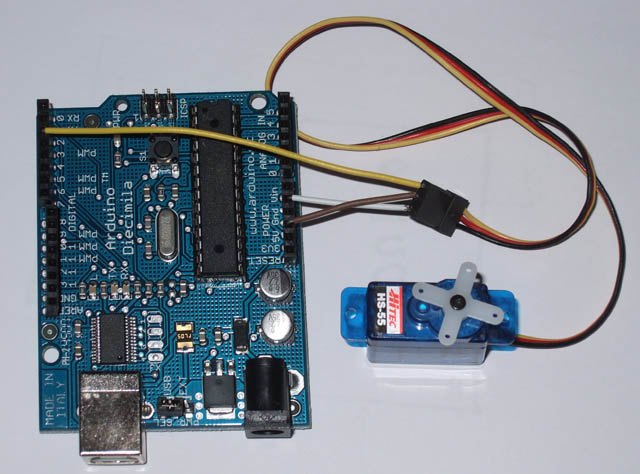
Servo motors have three wires:
power (RED),
ground (BLACK or BROWN), and
signal (YELLOW, ORANGE, OR WHITE).
The power wire should be connected to the 5V pin on the Arduino board.
The ground wire should be connected to a ground pin on the Arduino board.
The signal pin should be connected to a digital pin on the Arduino board.
***Note servos draw considerable power, so if you need to drive more than one or two, you'll probably need to power them from a separate supply (i.e. not the +5V pin on your Arduino). Be sure to connect the grounds of the Arduino and external power supply together.
***PAY CLOSE ATTENTION TO YOUR CONNECTIONS PRIOR TO POWERING (CONNECTING TO THE USB PORT). IF YOU ARE NOT SURE WHAT GOES WHERE PLEASE ASK. IF YOU REVERSE THE POLARITY OF THE SERVO YOU WILL FRY IT. THIS IS NOT GOOD....
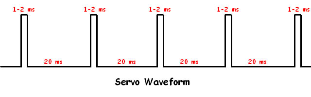
FYI: how servos work -->
Here’s the one minute overview of how you control servos. Most servos rotate 180 degrees. Servos are controlled by a single digital pin. The way to tell a servo what to do is by sending them a high pulse for a certain duration. Most standard RC servos use a pulse of 1 millisecond to indicate 0 degrees of rotation and 2 milliseconds for 180 degrees. That means 90 degrees is set via a 1.5 millisecond high signal.
One problem is that our servos have minimal memory. They forget how the most recent pulse you sent them was after 50 milliseconds or so. This means just telling a servo what what position to go to once is not enough. You need to constantly remind it by sending it a series of pulses, like this:
one advantage of using an arduino is that there is a library that makes sending your servo to a specific angle/position very straightforward:
the arduino servo library
once you are positive your servo is attached to your arduino correctly, open up the arduino IDE, and navigate to the servo sweep example like so:
file-->examples-->servo-->sweep
**notice that it defaults to attaching the servo to digital pin 9, if you've attached your servo to digital pin 2, as in the photo above, you can either move the wire to pin 9, or change the code to myservo.attach(2)
now program the arduino with the sweep code.
working?
let's study the code -->
// Sweep
// by BARRAGAN <http://barraganstudio.com>
// This example code is in the public domain.
#include <Servo.h>
Servo myservo; // create servo object to control a servo
// a maximum of eight servo objects can be created
int pos = 0; // variable to store the servo position
void setup()
{
myservo.attach(9); // attaches the servo on pin 9 to the servo object
}
void loop()
{
for(pos = 0; pos < 180; pos += 1) // goes from 0 degrees to 180 degrees
{ // in steps of 1 degree
myservo.write(pos); // tell servo to go to position in variable 'pos'
delay(15); // waits 15ms for the servo to reach the position
}
for(pos = 180; pos>=1; pos-=1) // goes from 180 degrees to 0 degrees
{
myservo.write(pos); // tell servo to go to position in variable 'pos'
delay(15); // waits 15ms for the servo to reach the position
}
}
now let's alter it to include some Serial.println() functions.
**remember to put the Serial.begin(9600) in the void setup () function
** then put two Serial.println(pos) function in the appropriate place in the void loop() function
now start making changes to the code that will affect the pos variable, and watch the movement of the motor while keeping an eye on the terminal window.
ok?
next, let's change the delay(15) function so that the number 15 is contained in a variable, let's call the variable t
look carefully at the sweep example and figure out how to change the 15 to a variable called t that contains the number 15.
next add another Serial.println(t) function in the appropriate place in the code.
try your code.
working?
now change the value in t to another number, and see what happens.
***
you don't have to use for loops for the servo, you can send the motor specific angles and then give it time to reach them, like this:
#include <Servo.h>
Servo myservo; // create servo object to control a servo
// a maximum of eight servo objects can be created
int pos = 0; // variable to store the servo position
void setup()
{
myservo.attach(9); // attaches the servo on pin 9 to the servo object
}
void loop()
{
myservo.write(90); // tell servo where to go
delay(250); // waits 250ms for the servo to reach the position
delay(3000); //remain at 90 degrees for 3 seconds
myservo.write(180); // tell servo where to go
delay(250); // waits 250ms for the servo to reach the position
delay(3000); //remain at 180 degrees for 3 seconds
}
combine for loops (sweeps), with direct movements, code
code flows from top to bottom, and repeats forever within the void loop() function
you can alter the code by adding additional for loops with whatever angles/t's (delays) you like.
try adding two new for loops with different numbers angles/t's, and see what happens.
work with adding new for loops that create smooth transitions between pairs of for loops
add as many for loops as you like to create a sequence of movements.
take a look at the parts that came with the servo. the gears that attach to the servo are called arms and sometimes horns.
for your assignment you'll be altering the sweep code and creating a modest project using the servo, by attaching something to it, and adding for loops.
***the servos you have are not very strong - you can damage them by asking them to move something heavy - work only with light materials for this project!
***save your code (via the save as... technique) frequently. before you leave, if you are not using your own laptop, you can copy and paste your code(s) into the body of an email.
combining reversible dc motors and servos, code.
assignment
create a motion study with the stronger DC motor and the servo
buy yourself a motor (see above)
have both motors change direction.

relays and other motors (blowers, pumps, solenoids)
how relays work
how to control them w/ the arduino
this omron has a 12v coil....

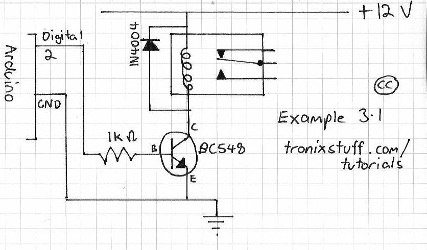
code:
void setup()
{
pinMode (2, OUTPUT); // set pin 2 as an output pin
}
void loop()
{
digitalWrite (2, HIGH); // turn on pin2 for 3 seconds, then off for 2 seconds
delay (3000);
digitalWrite (2, LOW);
delay (2000);
}
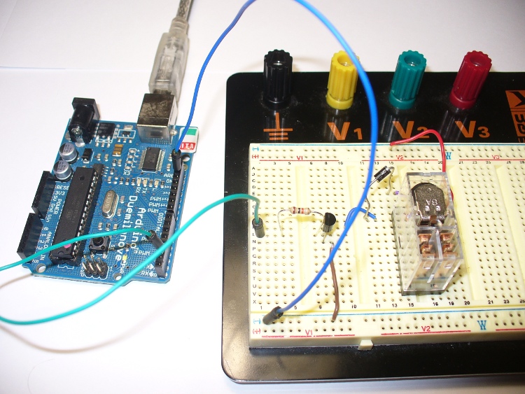
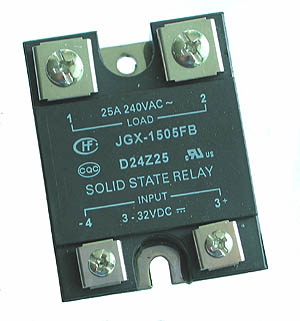
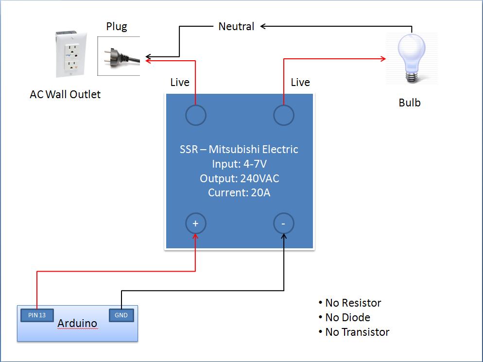
arduino + a Solid State relay:
code:
void setup()
{
pinMode (13, OUTPUT); // set pin 2 as an output pin
}
void loop()
{
digitalWrite (13, HIGH); // turn on pin13 for 5 seconds, then off for 3 seconds
delay (5000);
digitalWrite (13, LOW);
delay (3000);
}
how (and why) to combine arduino sketches.
for an excellent article/tutorial read this
how:
open up the two sketches you want to merge
arrange the arduino IDE so that you can see both sketches
you can't simply copy one sketch and paste it into another, because
duplications are bad!
duplicate variable names between sketches will cause chaos in your code.
if you have duplicate variable names in your two sketches then rename all of the duplicates in one of your sketches, i.e.,
sketch 1 has a variable (local or global) called
int val;
sketch 2 also has a variable (local or global) called
int val;
- highlight the word 'val' in sketch 2
- apple-f
- rename all of the instances of val to val1
- done.
see?
duplicate functions (including void setup and void loop) can only appear once in each sketch!
to review
arduino sketches have three parts:
comments
variables
processes
**aside from comments, nothing can be duplicated when merging two sketches.
- form small groups
- pool your resources (share)
- make a project that uses some combination of servos, reversible dc motors (via h-bridge) and one of the extra special relay controlled motors from today.
assignment
collaborative motor project
due at the end of class next week - meaning you can have the second half of class today and the first half of class next time to work on them.
collab crit (2nd half of class - first half is setup/finish...)
final project intro
assignment
document your collaborative project:
short video (2-3 mins max), edit in iMovie, or the editing software you prefer
include title screen with:
project title
date
names of artists
4 still images
bring the documentation next week and we'll look at it from the teaching station.
gather supplies for your final project, after the presentations of your documentation we'll work on your final projects and review what we've studied thus far
project documentation
exhibit planning
field trip to the gallery space
after the field trip we'll have a review session to prepare you for your final projects
assignment
assemble your plans and materials for your final project, the next two classes will be final project workshops so please be sure to bring materials for your final project to class
have a great thanksgiving!
show update
opening will be dec 14th - we'll coordinate times with ledelle
we need to have a title and brief description by friday to jack.
we'll setup a google group tonight and discuss scheduling
final project workshops tonight and next week
final crit can be friday, dec 14th in the gallery before the opening
assignment
please work on your final projects and bring materials to work on in class - if you'll be working in the gallery please let me know.
the show/final project workshop
the show will open on december 14 @6pm
food?
assignment
we should begin installing on site next week, let's coordinate whether we'll be meeting at copy cat or in station.
Learning Resource Center ADA Compliance Statement Any student who feels s/he may need an accommodation based on the impact of a disability should contact the instructor privately to discuss specific needs. Please contact the Learning Resource Center at 410-225-2416, in Bunting 458, to establish eligibility and coordinate reasonable accommodations. For additional information please refer to: http://www.mica.edu/LRC
Health and Safety Compliance
From the Office of Environmental Health and Safety (EHS)
It is the responsibility of faculty and students to practice health and safety guidelines relevant to their individual activities, processes, and to review MICA's Emergency Action Plan and attend EHS training. It is each faculty member's responsibility to coordinate with the EHS Office to ensure that all risks associated with their class activities are
in brief, if you do the work on the syllabus, don't skip class, return from dinner, are on time, participate in crits and are a good member of the class community you will earn at least a B. if you skip class, are late, don't do the work, fall asleep, are disruptive, and don't participate you will get lower than a B. if you are having trouble with the class it is your responsibility to meet with me so that we can work together to improve your experience.
the fast track to a low grade: skip crits.
***skipping crits without notifying me, in writing, prior to the crit and not doing/presenting the work due within one week will lower your final grade by one full letter grade for each crit you elect to ignore. We will have four crits during the semester so if you skip all of them you will fail the class.
to get an.....
A: perfect attendance, on time arrival at the beginning of class, on time return from dinner. never falling asleep during class, all assignments completed on time, active participation in all critiques, exceptional work, kind, courteous, generous member of the classroom community.
B: no more than one absence/one later arrival to class/one late return from dinner/one non-return from dinner. no falling asleep in class, all assignments completed on time, thoughtful, fully completed assignments, participation in all critiques. friendly classroom demeanor.
C: average engagement with class, no more more than two absences/occasional late arrival to class/occasional late return from dinner/occasional non-return from dinner. mediocre projects.
D: frequent absence, lateness, minimal effort on projects, minimal participation in crits.
F: general non-performance, including, but not limited to: minimal attendance, minimal work done, frequent absence, disruptive behavior, sleeping in class, etc.